Visualizing Communications: Modulation
In this series of blog posts I cover many components of a modern wireless communications system in the way that I personally learn best, through visualization and interaction. Each of these posts not only explains wireless communications, but includes interactive examples to visually explore how communications systems work.
In this post we cover modulation. Modulation is the way that data is added (or encoded) onto RF waves. This is extremely important to radio communications because it allows us to actually transmit data. Without modulation, a radio wave would consist only of a carrier frequency (a constant sinusoid at a single high radio frequency) but would not actually contain any data. Well if it doesn't contain data then theres no point, all we've done is create a fast sine wave... woopdi-freakin-doo.
In any modulation scheme we typically have two knobs we can turn (yes there are more like polarization and whatnot for all ye smartasses out there). These knobs are the amplitude (or magnitude) and the phase (or angle). We can think of the amplitude of the size of the wave, and the phase as the delay of the wave. If we increase the amplitude, the wave will be larger. If we increase the phase, we will expect the peak of that wave to show up earlier (think of it like moving waves coming into a beach). Typically though we do not refer to amplitude and phase, but to real (in phase) and imaginary (quadrature). All these are definitions do is allow us to refer to waves in rectangular coordinates as opposed to polar (circular) coordinates.
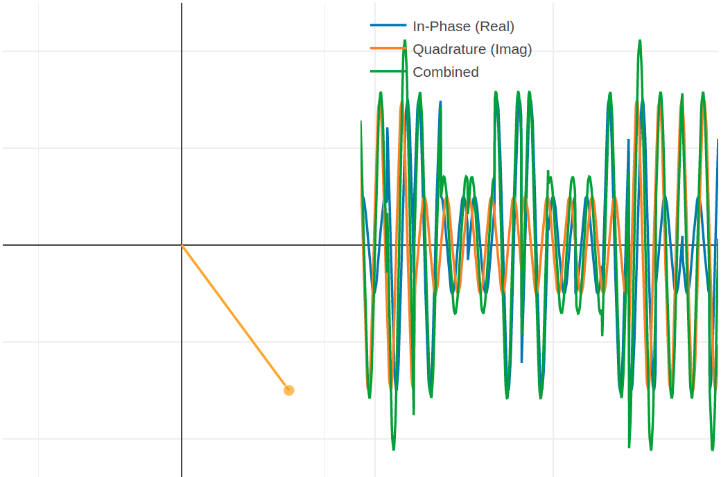
The sliders above let you see how changing the real and imaginary values effects the waveform. The left plot shows the real and imaginary values of the waveform on a rectangular plot (we will see more why this is important later) and the right shows a visualization of the waveform over time. The plot on the left is not actually the waveform, but just a plot of what the real and imaginary (or magnitude and phase) values are for any given waveform.
If at any point during this tutorial you would like to play around with the waveform plots click "Free Play" at the top of the screen.
Analog Modulation
Let's begin with some modulation schemes you likely have heard of, Amplitude modulation (AM) and frequency modulation (FM). These are the same types of modulation schemes used for your typical radio in your car (or wherever you may have an AM/FM radio). While these types of modulations can also be used to transmit digital data (as we will talk about in the next section with ASK and FSK), originally these types of modulation were used to transmit analog signals (Analog signals can be thought of as an oscillating waveform while digital signals are a stream of discrete 1s and 0s).
Amplitude modulation (AM)
For the longest time, AM radio dominated the market. The biggest thing is that it is extremely simple to build. It can be constructed with a few passive components (e.g. Resistors, Inductors, Capacitors) and a minimal number of active components (Transistors) to combine the high frequency radio wave with a lower frequency sinusoid that contains our data. In the case of your AM radio, this would be a sound wave. Click 'Try It' below to see what amplitude modulation looks like if we repeatedly transmit the same data.
In the case of an AM radio, this tone we modulate onto the radio frequency would be recieved on the other side and played through a speaker to create a sound. In this case because we are repeating the same thing over and over again, we would only hear a single tone coming out of the speaker. In a more realistic scenario the data we are modulating onto our rf carrier frequency (again the high frequency that "carries" the data) will be much more complex to produce music or a voice at the output.
Phase Modulation (PM)
Before we get into frequency modulation, I would like to look at a similar (but less well known) modulation type. This is phase modulation. Similarly to amplitude modulation, as we have a waveform of data we want to transmit, we adjust our phase of our wave based on the magnitude of the data we receive. You can likely see why this is not as common as it is much more difficult and provides minimal to no gain over using amplitude modulation. Click 'Try it' below to see phase modulation in action.
Frequency Modulation (FM)
Finally we have frequency modulation. This has been the standard for things like car radios for years. It provides better noise reduction over AM by spreading the data across a larger number frequencies. That way, even if there is other data being transmitted at one of the frequencies used in FM, its likely the majority of the data (or in many cases music) can get through with minimal interference. You will see we don't have the same nice visualization for this. Well this actually twists a different "knob" than the other two because we are adjusting the frequency as opposed to the magnitude or phase. You may ask "Why don't we adjust all three?". It unfortunately is not that simple. As we add data onto our carrier frequency, we actually spread the power away from our carrier frequency. FM just does this in a much more efficient (e.g. interference protected) way than AM.
I thought about adding a nice visualization for FM, but it required a large amount of programming just for this example... so sorry I didn't do that. The thing is that analog modulations are really becoming a thing of the past. While FM outperforms AM and PM, it still can have a lot of noise (I actually live in a fun place that receives delayed version of the same station, but that's a story for another time). It also requires somewhat complex signal processing on the analog signals if you want to improve the signal at the reciever.
Digital Modulation
The best way to transmit data is through one of many digital modulation schemes. Unlike analog modulations, digital modulation provides discrete 1 or 0 values (i.e. bits). These bits are then streamed in the order they are received to represent digital data. This opens up a world of possibilities. For example, we can add binary data encoding schemes to allow us to know (and in some cases fix) any bits that may have been incorrectly received. We could also compress the data (think a .zip file) before we send it so we have to send less data overall (depending on what we are transmitting). For this and many MANY other reasons (security for one), most modern systems are trending toward digital modulation schemes for wireless communications, including the radio in your car.
The first three modulations schemes in this section are derived directly from our analog modulation schemes. The amplitude and Phase shift keying though are the groundwork for quadrature amplitude modulation (QAM) which is used in the majority of digital wireless communications today.
Keep in mind that while the output waveform may be difficult for you to tell the difference in, circuits and computers are easily able to decipher each of the states and accurately extract the bits from received data. In the majority of these cases, it is more useful to look at the real-imaginary plot on the left side than the time domain waveform. The real-imaginary plot is what the receiver will ultimately be using.
Amplitude Shift Keying (ASK)
For each of the analog modulation schemes, there is a digital counterpart. For example, AM can be used in an on/off (or almost off) fasion to provide 1s and 0s. An example of this can be seen with the 'Try It' button below.
In this visualization, we can see that by quickly shifting the amplitude between two states, we can transmit a 1 as a high level and a 0 as a low level. While this doesn't transmit as much information as AM, it is much more robust because our value is one of only two states so noise will only effect it if we receive the incorrect state.
Phase Shift Keying (PSK)
We can also use a discrete version of PM to again transmit 1s and 0s. By shifting between two discrete phase values, we are able to denote a phase value as a 1 and a phase value as a 0.
Frequency Shift Keying (FSK)
Similarly to FM, we can jump between frequencies to transmit bits. In this case, we will jump between two predetermined frequencies. One frequency will denote a 0 and the other will denote a 1. Unlike FM this type of digital communications is relatively uncommon. One commercial application I have seen of this is transmission between SCUBA dive computers and wireless gas pressure monitors. There is nothing wrong with FSK (well besides it is inferior to more modern modulations we will look at in a second), but again it is more difficult than ASK or PSK to implement
π/2-Binary Phase Shift Keying (BPSK)
Now we are moving into more modern communications schemes. The pi/2-BPSK is actually nothing more than a form of PSK. All we do for this type of modulation is shift between two phase states allowing the transmission of binary data. Again, in this modulation scheme we are only transmitting either a 1 or a 0.
Quadrature Phase Shift Keying (QPSK)
Now is where things get more interesting. Instead of sending only a single 1 or 0, if we increase the number of possible real and imaginary (magitude and phase) states that our waveform can be in, we can actually send two bits. In the case of QPSK we have 4 distinct states in what is called a constellation. Each of these states represents two bits. Each of the four states represents one predetermined value of either 00, 01, 10, or 11. Assuming no errors in transmission and no hardware limitations, this allows transmitting data at twice the speed of BPSK, ASK, PSK, or FSK. The 'Try It' button below will show a waveform cycling through each of these four states. These bits would then be stacked into a single stream of data like in any other digital modulation scheme.
M-ary Quadrature Amplitude Modulation (M-QAM)
But why stop there? We can then extend this further to not only transmit two bits, but we can transmit three, four, five, and more bits at the same time by simply increasing the number of possible discrete states or points in our constellation. It is common to use 16-QAM, 64-QAM, and 256-QAM nowadays. It is likely your home wireless router implements all of these modulation schemes. Some systems will take this even further up to 4096-QAM and beyond to further increase the amount of data that is transmitted at a single point in time. The 'Try It' button below will show cycling through each of the states of a 16-QAM modulation scheme.
While this visualization repeats itself, in actuality we would move to each point in the constellation in a specific order to represent the data that was sent. Then when this data is received it can be decoded into sound, an email, or this webpage!
Why don't we always use the highest order QAM?
Now that we have seen all of the different version of modulation, you are likely asking "why don't we just always use the highest M-QAM possible?". Well again it comes down to noise. As we increase the value of M in our M-QAM modulation, the distance between each of our points in our constellation reduces. As these points get closer, we begin to incorrectly receive more and more bits. If we receive enough incorrect bits, the highest possible M-QAM scheme will begin to have a lower data rate than if we were using a lower value of M.
Typical systems like a cellphone will therefore switch between BPSK, QPSK, 16-QAM, 64-QAM, and 256-QAM on the fly to provide the best possible data rate for the current given noise level.
Smoothing the Transitions
As you may have noticed, the digital modulation schemes have some rough edges when we transition from one position to another. We can introduce some tricks that relieve these sharp changes (transients) which could cause issues if we actually try to implement this. This though is a topic in its own that requires further explanation of how frequency plots of waveforms look and how we can shape these waveforms to provide desirable time and frequency domain responses.